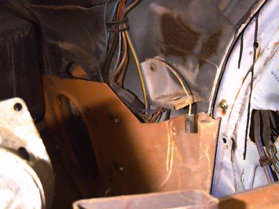
70-79 Trans Am Power Windows Page

This page shows some of the wire routing in 1970-81 Trans Ams with power windows. The 1970-79 systems are practically identical. In 1980, the fusebox was updated (it's illustrated below), and the power supply was changed quite a bit. The regulators are the same, though.

1970-79 Fusebox

The 70's Trans Am Fusebox had a single terminal for ignition accesories. Add-on items like cruise control, tachometer, and power windows were all run off this terminal. If you had several of these options, you'll have several jumpers that allow everything to feed on this circuit. The power windows didn't get their power from this terminal; it was just used to turn them on. The power came through the 30 amp circuit breaker.
fuse box

1980-81 Fusebox

In 1980 Firebirds changed to blade fuses. In the left view, the top circuit breaker powers the windows through a pink wire. In the right view, the circuit breaker is removed, and you can see where the big pink wire snaps into a socket in the fuse box. This pink wire goes straight to the switch, so there is no relay. The lower circuit breaker marked "power access" is for the rear defroster.
fuse boxfuse box
Relay

Relay

This relay, mounted where you'd never find it, was used to turn the power windows on and off on 1970-79 models. This kept the considerable amperage of the system off the ignition switch and accesory terminal. Unfortunately, the full amperage did go through the console-mounted switches, so the wiring in the console is often toasty 30 years later.

If you don't recognize this location, that big bolt to the left of the relay is one of the two steering column mounting bolts. The brake pedal is hanging down in the center of the picture.

Note: This relay wasn't used in 1980-81.

Door Regulator

The power window regulator mounts in different holes from the manual, and is oriented differently. This can be confusing if you're doing a conversion.These holes may not even be drilled on your door.

This is a 1980 door with original power windows. Early 70's doors use a different stamping, but the regulator holes are in the same locations. The purple box shows approximately where the motor will be.

These doors are all spot-welded by hand along the bottom. They appear to be cut, modified, and welded back together. I can't imagine why this was done, but it's original.

Door

See the motor?

See the Motor?

This picture simply shows where the motor is supposed to end up. The electrical plug is visible through the big hole nearest to the camera.

Wiring

The power window (and door lock) wiring was kept tidy in a plastic gutter that runs along the firewall.
Conduit1Conduit2

What is this stuff?


Above:

Wiring to the power supply and relay goes into the middle of the conduit. Wiring for the switch and left door comes out of the left end. This particular car is a 79 with power door locks (which are different from 70-77 doorlocks). The locks contribute more wires to the picture than the windows.

Right:

The wiring on the right end is power window, power door locks, and 2 rear speakers. The white wire dangling is from the door jamb switch. The speaker wire goes under the carpet from here.

As the wiring comes out of the right end of the conduit and goes behind the kick panel, there are plugs in everthing going to the door. The power windows wires are the blue and gray wires coming out through the door frame at far right.


Below:

Behind the left kick panel are wiring for the locks (left plug), the power window switch (right plug), from the switch to the left power window motor (middle), taillamps (in black conduit), and rear defroster (the big purple wire).
Conduit3
left side